文章目录
- Arduino, I used a Pro Mini clone but any Arduino will do as long as it can be fit inside Buzzer Some wires
- Download the X6-Timer Arduino code and upload it to your Arduino board. You will need these libraries to compile the code. https://github.com/olikraus/U8glib_Arduino https://github.com/arkhipenko/TaskScheduler Carefully open the case of your X6. Locate the VCC and GND pins as the pictures shown below. Use a multimeter to verify (you will need to turn the radio on to get the voltage reading, it should be the voltage of your batteries), turn off and unplug the battery lead after that. Solder a pair of power wires to the indicated pins. Locate the ARM pin, it’s the outside pin that has a red wire connected to it. The other end of the red wire connects to CH5 on the main circuit board. Note that I have swapped the switches of CH5 & CH6, so mine ARM switch is on the right if you look from the back of the radio. If you haven’t done so your ARM switch is on the left. Solder a wire to the pin as picture shows. Solder the parts according to the diagram (I admit this is not the best drawn but you get the idea). Tape or hot glue the Arduino and buzzer to the inner side of the radio as shown. I used 3M double-sided tape. Double check all leads are firmly soldered and not shorting anything. You are warned. Put back the battery leads and the case.
- Beep code: 2 ascending tones means ‘Armed’. 2 descending tones means ‘Disarmed’. A short beep means 1, a long beep means 5. Turn the radio on with your [ARM] switch at the [disarmed] position, you should hear 2 descending tones. Flip the [ARM] switch to the [armed] position, you should hear 2 ascending tones. Keep the switch in the armed position, you will hear 3 short beeps at 3 minutes, 1 long beep followed by 2 short beeps at 7 minutes and so on. Flip the [ARM] switch to the [disarmed] position, you should hear 2 descending tones. That’s it! Personally, I am very satisfied with this ‘elegant’ mod. And it works like a charm.
- The frequencies I used to drive my buzzer may not work well for yours. Feel free to play with the numbers to find out the best value for your buzzer. The 2 tones you hear when powering up the radio is actually the indication of the position of the [ARM] switch. When you hear ascending tones when powering up you know your ARM switch is in the wrong position. The code provided also draws the actual time numbers to an OLED screen. Feel free to add one of the most common 0.96” OLEDs if you like to have a visual indication. Simply glue it to the front of the radio, snake the wires through the hole where the CH7 switch would be, connect them to the I2C pins on the Arduino and you are good to go.
If you fly an XK K110 or XK K120 micro helicopter you probably own an XK X6 transmitter. I personally consider it to be a really cheap and cheerful entry-level hobby grade radio as it’s not fancy but offers the most basic features you need at a very low price. The only complaint most of us have is it lacking a timer.
I do enjoy flying my XK micro helis with the X6 and I think it does a decent job. But I also want a timer to avoid any unexpected drop-off without spending a fortune to buy a FUTABA. So, I decided to do a mod.
Due to my laziness, I want this mod to be simple to do and stupid to use:
- No extra power source needed, no extra power switch needed. It takes power directly from the main batteries and powers on and off with the transmitter simultaneously.
- No drilling holes needed. Nothing dangling outside. The radio will still be perfectly intact.
- Works with all models without messing around with the radio’s settings.
- No need extra button clicks or anything else that I may forget to do in the field.
- Low cost.
In short, ‘plug and forget’. The idea I came up with was to use an Arduino to monitor the radio’s ARM switch(aka the Throttle-Hold switch, the same below), start the timer when armed(throttle is active), stop when disarmed(throttle is inactive), and beeps on full minutes.
- Arduino, I used a Pro Mini clone but any Arduino will do as long as it can be fit inside
- Buzzer
- Some wires
- Download the X6-Timer Arduino code and upload it to your Arduino board. You will need these libraries to compile the code.
https://github.com/olikraus/U8glib_Arduino
https://github.com/arkhipenko/TaskScheduler
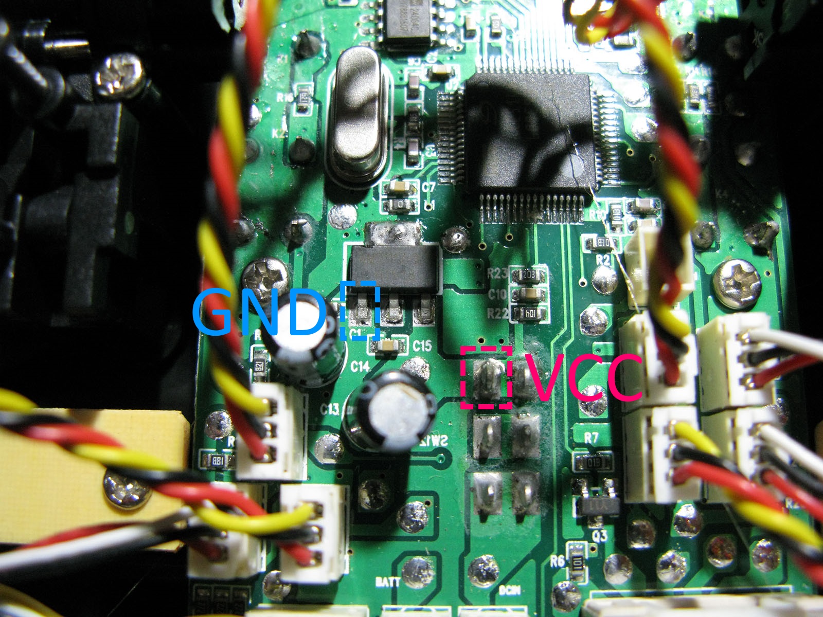
- Carefully open the case of your X6.
- Locate the VCC and GND pins as the pictures shown below. Use a multimeter to verify (you will need to turn the radio on to get the voltage reading, it should be the voltage of your batteries), turn off and unplug the battery lead after that. Solder a pair of power wires to the indicated pins.


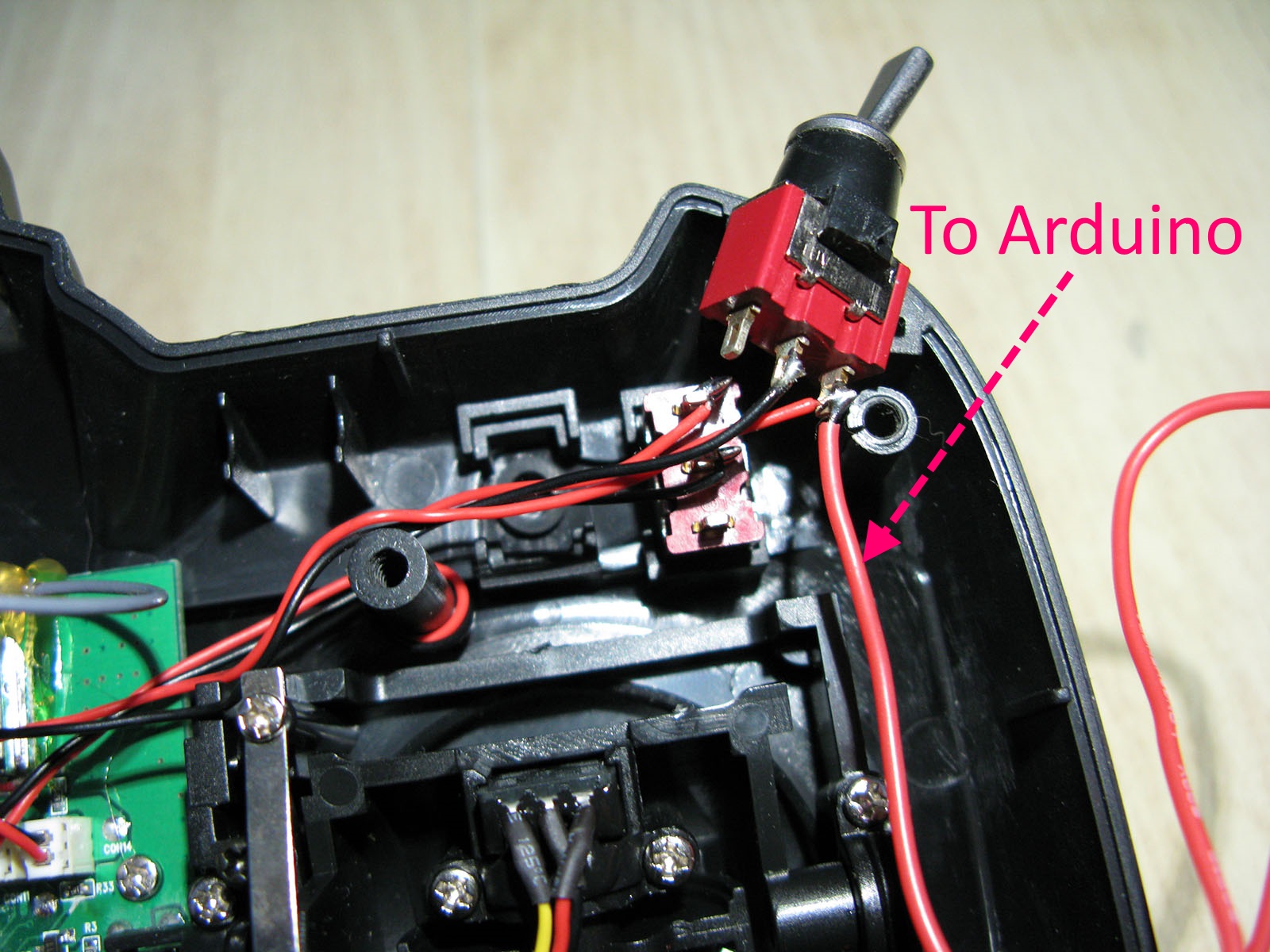
- Locate the ARM pin, it’s the outside pin that has a red wire connected to it. The other end of the red wire connects to CH5 on the main circuit board. Note that I have swapped the switches of CH5 & CH6, so mine ARM switch is on the right if you look from the back of the radio. If you haven’t done so your ARM switch is on the left. Solder a wire to the pin as picture shows.
- Solder the parts according to the diagram (I admit this is not the best drawn but you get the idea).

- Tape or hot glue the Arduino and buzzer to the inner side of the radio as shown. I used 3M double-sided tape. Double check all leads are firmly soldered and not shorting anything. You are warned.

- Put back the battery leads and the case.
https://github.com/olikraus/U8glib_Arduino
https://github.com/arkhipenko/TaskScheduler
- Beep code: 2 ascending tones means ‘Armed’. 2 descending tones means ‘Disarmed’. A short beep means 1, a long beep means 5.
- Turn the radio on with your [ARM] switch at the [disarmed] position, you should hear 2 descending tones.
- Flip the [ARM] switch to the [armed] position, you should hear 2 ascending tones.
- Keep the switch in the armed position, you will hear 3 short beeps at 3 minutes, 1 long beep followed by 2 short beeps at 7 minutes and so on.
- Flip the [ARM] switch to the [disarmed] position, you should hear 2 descending tones.
That’s it!
Personally, I am very satisfied with this ‘elegant’ mod. And it works like a charm.
- The frequencies I used to drive my buzzer may not work well for yours. Feel free to play with the numbers to find out the best value for your buzzer.
- The 2 tones you hear when powering up the radio is actually the indication of the position of the [ARM] switch. When you hear ascending tones when powering up you know your ARM switch is in the wrong position.
- The code provided also draws the actual time numbers to an OLED screen. Feel free to add one of the most common 0.96” OLEDs if you like to have a visual indication. Simply glue it to the front of the radio, snake the wires through the hole where the CH7 switch would be, connect them to the I2C pins on the Arduino and you are good to go.


暂无评论